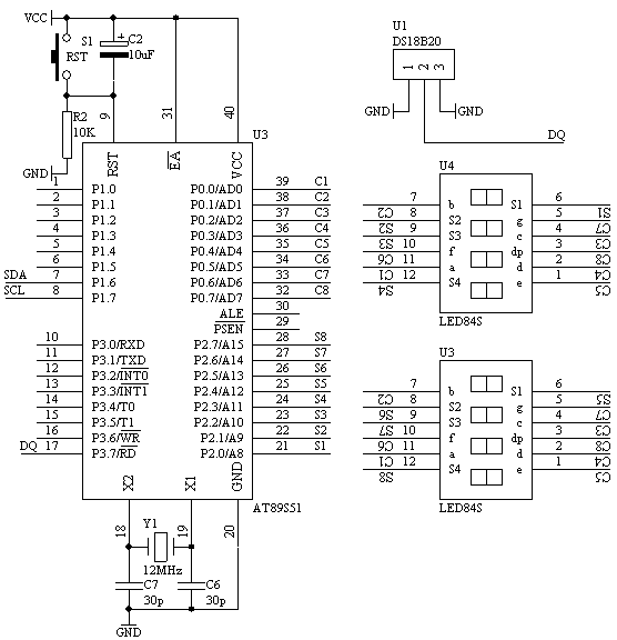
5. 电路原理图

6. 系统板上硬件连线
(1). 把“单片机系统”区域中的P0.0-P0.7用8芯排线连接到“动态数码显示”区域中的ABCDEFGH端子上。
(2). 把“单片机系统”区域中的P2.0-P2.7用8芯排线连接到“动态数码显示”区域中的S1S2S3S4S5S6S7S8端子上。
(3). 把DS18B20芯片插入“四路单总线”区域中的任一个插座中,注意电源与地信号不要接反。
(4). 把“四路单总线”区域中的对应的DQ端子连接到“单片机系统”区域中的P3.7/RD端子上。
7. C语言源程序
#include <AT89X52.H>
#include <INTRINS.h>
unsigned char code displaybit[]={0xfe,0xfd,0xfb,0xf7,
0xef,0xdf,0xbf,0x7f};
unsigned char code displaycode[]={0x3f,0x06,0x5b,0x4f,
0x66,0x6d,0x7d,0x07,
0x7f,0x6f,0x77,0x7c,
0x39,0x5e,0x79,0x71,0x00,0x40};
unsigned char code dotcode[32]={0,3,6,9,12,16,19,22,
25,28,31,34,38,41,44,48,
50,53,56,59,63,66,69,72,
75,78,81,84,88,91,94,97};
unsigned char displaycount;
unsigned char displaybuf[8]={16,16,16,16,16,16,16,16};
unsigned char timecount;
unsigned char readdata[8];
sbit DQ=P3^7;
bit sflag;
bit resetpulse(void)
{
unsigned char i;
DQ=0;
for(i=255;i>0;i--);
DQ=1;
for(i=60;i>0;i--);
return(DQ);
for(i=200;i>0;i--);
}


 Alexa
Alexa mcusy_cn#126.com (请把#改成@)
  交流:522422171
 51/AVR单片机技术驿站! <


 最新评论
最新评论